Diode Laser Cladding: How it works / Process overview
Introduction
The cladding of components is a well-established practice which can improve the wear resistance, corrosion resistance and / or hardness of the surface of the component. It is generally used in two scenarios:
- Where significant improvement to the base material is required, e.g. mechanical properties, because manufacture of the whole of the component out of the clad material would not be cost effective.
- To repair damaged or worn in-service components, and achieve the necessary high level of mechanical properties at the damaged section of the component.
Cladding creates a new surface layer from a different material to that of the substrate. This new layer is bonded to the substrate through fusion. This is in contrast to processes that purely alter the microstructure of the substrate surface, such as heat treatment, carburising or nitriding, in order to improve the mechanical properties of the surface.
Although cladding has been around for some time, the use of lasers as the heat source is relatively new (from around the 1970’s (1)) and even more so the use of diode lasers is still in a ‘further development’ stage. Typical materials used to clad inexpensive substrates include nickel alloys, stainless steels and titanium alloys.
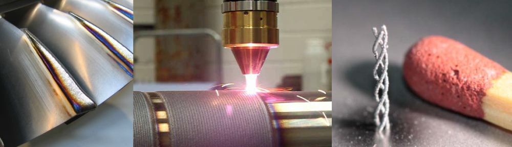
In Figure 1, the typical arrangements within the nozzle of a diode laser cladding manipulation system and the fusion process can be seen. The various aspects of the process will be discussed throughout this section.

Figure 1: Typical Diode Laser Cladding (2)
Equipment
Two distinct types of diode lasers are available; direct diode laser and fibre-coupled diode laser. In the case of a direct diode laser system the laser is at the end of the manipulation system next to the powder nozzle, while in the case of a fibre coupled diode laser systems the laser light is conducted via a glass fibre to the nozzle.
Either system is very compact but the fibre coupled diode laser system has a couple of advantages compared to the direct laser, namely:
- The laser is separated from the cladding process and from the manipulation movement thereby preventing accidentally damage and operation-related fouling.
- The clad head is much lighter, consequently reducing the weight requirements of the manipulation arm.
- One laser unit can be used for different fabrication units with up to 6 beam exits.
- The modular structure allows easy upgrade to higher laser powers.
- With the use of specialized nozzles, the internal faces of components may be accessed.
The clear disadvantage of the fibre coupled system is the requirement of a glass fibre optic delivery system.
These differences can clearly be seen in the images below, with the clad head more remote on the fibre-coupled type.

Figure 2: A HighLight 8000D 8 kW high power direct-diode laser system performs large area laser cladding of Stellite 6 on flat and round low carbon steel materials (3)

Figure 3: Fibre coupled Laserline diode laser system (4)
The nozzle, as well as delivering the laser beam and the powder, also channels the gases through to the workpiece. Typically argon is used as the shielding gas to prevent oxidation of the cladding when applied and as it cools.
As the laser beam reaches the workpiece it locally melts the substrate surface and the powder being deposited, forming a melt pool and facilitating the fusion of the two molten faces – where the powder meets the substrate. As the nozzle continue on, the processed area cools and the clad forms a strong bond onto the substrate.
Lasers
The key to the successful further development of diode laser cladding is, of course, the quality, power and suitability of the laser. Current development work is focussing on achieving successful clad outcomes with lasers of around 20kW power although currently viable results are being achieved around the 10kW mark (5). The video (6) shows how Stellite material is applied at 8kW power on both circular and flat components. Of particular note is the flatness and uniformity of the cladding and how well the adjacent layers tie-in together.
https://www.youtube.com/watch?v=PN5MWELakZs (6)
There is a particularly key factor regarding the laser intensity profile that has great impact on the capabilities of the process. A round spot is the usual shape derived from a laser beam and this will give a Gaussian distribution of the beam intensity resulting in a high level of power at the centre of the distribution, but petering out to zero intensity towards the edges. However, the beam can be transformed into a ‘top-hat beam’ that provides a flat intensity profile. This effect can be seen in Figure 4, below. Note, the top-hat beam will still have some smoothed edges and this can be approximated to appear as a supergaussian profile.

Figure 4: A flat-top beam profile (red) in comparison to a Gaussian (green) and super-Gaussian (blue) intensity profile. All three beams have the same optical power and the same effective mode area. (7)
The advantage of achieving the top-hat beam intensity in diode laser cladding is that a wider area can be clad, with uniform coverage, than could be achieved with a spot. The transformation is achieved through the use of a suitable optical element such as aspheric lenses or diffractive optics. (7)
A diode laser is a semiconductor and its function is to convert electrical energy into laser light. The light energy striking the workpiece, melting the clad metal and forming the melt pool, is built-up from an array of numerous individual diode laser emitters, each producing a divergent cone of light. They are grouped together, in water-cooled linear bars and horizontal and vertical stacks, onto a single monolithic substrate, see Figure 6 (8).

Figure 5: A single diode laser bar mounted on a Micro Channel Cooled Package (MCCP) (8)

Figure 6: Diode laser bars stacked together (8)
Deposition
There are two main methods in which the cladding material can be deposited onto the surface of the substrate. Although wires or strips can be fed, the most common and preferred option is by the delivery of a jet of metallic powder. The powder is carried through the nozzle of the robot head by a carrier gas (typically argon). As can be seen from Figure 7 this can be achieved laterally, radially or coaxial.

Figure 7: Alternative feeding systems for laser cladding, a) wire feeding, b) lateral powder feeding, c) radially symmetrical powder feeding, d) coaxial powder feeding (9)

Figure 8: Typical configuration for powder and wire deposition with a line beam output (8)
Using a configuration of laser beams in a line set-up offers alternatives of powder or wire deposition. Figure 8 shows the difference between powder and wire cladding using the line beam output. Clearly in terms of coverage rates achievable powder represents the more viable option.
Heat affected zone and dilution
One of the great advantages of the power beam welding processes (laser and electron beam) is the minimal size of the heat affected zone (HAZ). Of course this principle applies in diode laser cladding. The lower heat input into the fusion region of the substrate material results in a HAZ that is much smaller than would be achieved by submerged arc or electroslag cladding, Figure 9.
Similarly, dilution – the change in composition of the clad metal through mixing with the substrate parent metal in the fusion zone – can be kept desirably low, typically less than 5%, meaning the vast majority of the bonded layer retains optimal desirable properties (8), (10). Such levels of dilution help provide better process controls and results in limited component distortion and corrosion susceptibility (11).

Figure 9: Cropped section of the diode laser cladding process highlighting the heat affected zone (2)
Induction Assistance
As with welding processes, pre-heating the work-piece can sometimes be necessary to help promote positive outcomes. One method of achieving this is currently being investigated by the Fraunhofer Institute (research and development centre in Dresden, Germany) and the impact that induction heating has on the cladding process. From Figure 10 it can be seen that the use of inductive heating can prevent cracking and enable multi-layering to be carried out with more confidence.

Figure 10: The effect of inductive heating (example shown is the cladding of Ti-43Al-4Nb-1Mo-0.1B onto Ti6Al4V) (2)
Induction heating can also increase deposition rates by 1.5 to 2 times due to the raised initial temperature. The following images clearly demonstrate the improved quality of the deposition, in this case through the use of a technique called ‘Induction Assist’. (10) The cracks highlighted in the dye-penetrant non-destructive testing results, would render using the process without inductive heating as a total non-starter. However, as the use of induction heating results in a limited flexibility in the process (difficulties applying the coil to the part) slower deposition rates may have to be employed to avoid such cracking where induction heating is not practical or even physically possible.

Figure 11: Improved deposition quality using ‘Induction Assist’ (10)
Cladding Outcomes
With due consideration for all relevant process variables, an optimised diode laser cladding process would be expected to produce a cladding of high quality, with the following key attributes:
- Very low levels of dilution.
- Free from porosity, completely dense.
- Suitably strong bond to the substrate.
- Fine metallurgical structure.
- Rapid deposition rate.
- Uniform, well controlled thickness and width.
- No / little distortion.
- Small HAZ.
- High material utilisation.
- No cladding cracks.
The following image, with its associated data, gives a good visual indication of what can be achieved with this process – the example given for 0.8mm clad thickness and a deposition rate of 20g/min. (8)


Figure 12: Cladding of 3550 Stainless Steel onto a substrate of 1018 steel (8)
Bibliography
1. Industrial Laser Solutions for Manufacturing. [Online] PennWell Corporation2014. [Cited: 14 November 2014.] http://www.industrial-lasers.com/articles/2009/06/laser-cladding-with-direct-diode-lasers.html.
2. Fraunhofer IWS; Technische Universitat. Additive laser processes for applications aircraft engine technologies. [Seminar presentation] Dresden : Fraunhofer IWS; Technische Universitat, 2013.
3. Olof, Andersson and Keith, Parker. High Power Diode Laser Cladding. Fabricating & Metalworking. March, 2014.
4. Laser Cladding. [Online] Stork Gears & Services BV, 2014. [Cited: 14 November 2014.] http://www.stork-gears.com/downloadables/flyer_laser_cladding.pdf.
5. Statistical analysis and optimization of processing parameters in high-power direct diode laser cladding. Liu, Shuang and Radovan, Kovacevic. 5-8, s.l. : Springer, 2014, Vol. 74. 1433-3015.
6. Laser Cladding. [Video] s.l. : Coherent, 2014.
7. RP Photonics Encyclopedia. Flat-top Beams. [Online] RP Photonics Consulting GmbH, 2014. [Cited: 14 November 2014.] http://www.rp-photonics.com/flat_top_beams.html.
8. [Online] 2014. [Cited: 14 November 2014.] http://www.coherent.com/downloads/CladdingWithHPDDL_WhitepaperFinal.pdf.
9. Baufeld, B. Cladding Desktop Study . Sheffield : Advanced Manufacturing Research Centre, 2013.
10. Fraunhofer USA. Possibilities for High Deposition Rate Cladding: High Power Lasers and Hybrid Techniques. [Seminar Presentation] Detroit : Fraunhofer USA, 2013.
11. Trends in Welding Research. David, Stan A, et al., et al. Ohio : ASM International, 2009. 139781615030026.
